Operating Principles and Efficiency
Gravitational Classifier
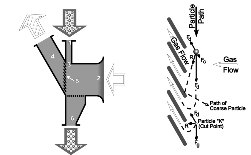
The simple design and operating principles of the gravitational classifier are demonstrated in Figures 1 and 2.

Feed material is dropped in a continuous feed curtain and enters the classifier at the top of the unit (1). Low velocity air enters the classifier at inlet (2) and is forced through the feed curtain (3) which is dropping in front of the air outlet (4) provided with widely spaced vanes (5). The air stream enters the feed curtain perpendicularly, but is changed to an almost parallel, but reverse, direction to the feed curtain as it passes through the vane.
Each particle entering the classifier has a gravitational force (FG) proportional to its mass, which in turn is proportional to the cube of its diameter. The particle is also subjected to a drag force (FD) proportional to the square of its diameter, created by the air flow through the feed curtain. As the particle is influenced by the drag force (FD) and changes direction, it is subjected to a small, centrifugal force (Fc) proportional to its mass, directly opposing drag force (FD). Under set conditions, the resultant force (R), acting on a particular particle diameter (K) referred to as the cut point, will be of a magnitude and direction such that the particle will either be swept through the vanes by the gas stream or impinge on the vanes, throwing it back into the feed curtain. The resultant force (r) on particles larger than (K) is in a direction at small variance with the gravitational force (FG). These particles will either impinge on the vanes and be knocked out or will fall directly into the coarse discharge outlet (6). Smaller particles will have a resultant force (R) almost parallel to the drag force (FD), permitting them to be swept through the vanes and collected by a filter.
Van Tongeren gravitational classifiers separate particles at any predetermined cut point between 2 mm to 150 micron (10 to 100 mesh). The cut point is controlled by the air velocity through the vanes, which determines the magnitude of drag force (FD).
Power requirements are extremely low; most energy lost is due to the change of direction of the air stream as it is exhausted through the vanes.
Gravitational-Inertial Classifier
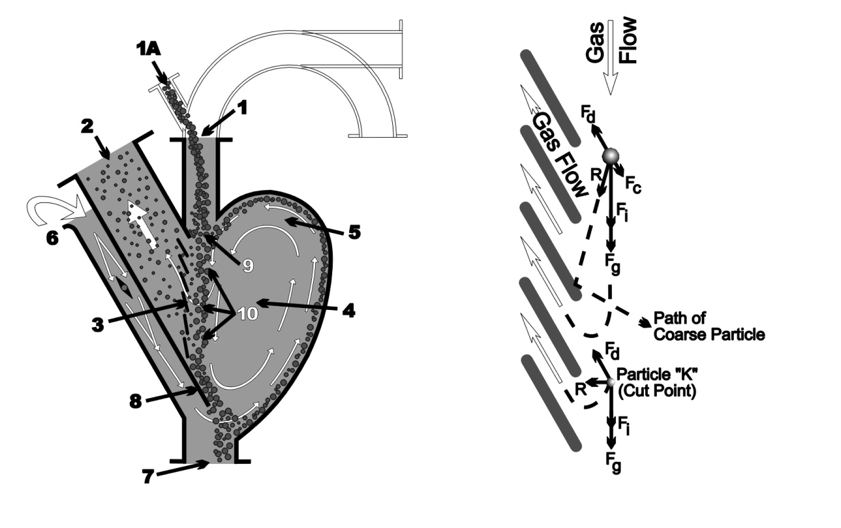
Gravitational-Inertial classifiers utilize classifying principles combining gravitational, inertial, centrifugal, and aerodynamic forces. Figures 3 and 4 graphically illustrate the operating principles.

Air- or gas-entrained feed material enters the classifier primary air inlet (1). Mechanically fed material is introduced at point (1A).
The curtain of feed material drops in front of the air outlet (2) which is provided with widely spaced vanes (3) almost reversing the gas flow introduced through the primary air inlet (1). Prior to passing through the vanes, the friction of the relatively high velocity causes the particles to flow in a counterclockwise current (eddy) (5) in the chamber (4).The eddy is reinforced by gas entering through the secondary air inlet (6) located just above the coarse discharge outlet (7).
Each particle entering the classifier has a gravitational force (FG) proportional to its mass, which is in turn proportional to the cube of its diameter. As the particle is introduced into the classifier primary gas stream, it is further subjected to an inertial force (Fi) also proportional to its mass.
Because the gas stream flows in a downward direction, the inertial and gravitational forces (Fi) and (FG) complement each other. As it passes through the vanes, the gas stream changes direction, exerting a drag force (Fd) proportional to the diameter of the particle and approximately opposite in direction to the gravitational and inertial forces. As the particle is influenced by the drag force (FD) and changes direction, it is subjected to a centrifugal force (Fc) proportional to its mass, which directly opposes the drag force (FD).
Under design condition, the resultant force (R) acting on a particular particle diameter (K) (cut point) is of a magnitude and direction to cause the particle to either be swept through the vanes or be thrown back into the feed curtain. The resultant force (R) on particles larger than (K) is in a direction at small variance with the gravitational-inertial forces. The particles will either impinge on the vanes and be knocked out or fall directly into the coarse discharge (7).
The eddy current (5) flowing downward, parallel to the place formed by the vanes, provides a moving wall containing the curtain of feed material in the classifying zone without the detrimental frictional drag effects of a solid wall.
The particles not swept through the vanes fall onto an inclined baffle plate (8) located at the bottom of the gas outlet (2) directly beneath the primary gas inlet (1). The coarse product is scrubbed by the secondary air as it slides off into the coarse discharge outlet. Secondary air flow dislodges any fines adhering to coarser particles. They join the stray fine particles entrained by the eddy current and are returned to the classifier inlet point (9) and reintroduced into the classifying zone (10).
Van Tongeren Gravitational-Inertial classifiers separate particles at any desired cut point from 300 to 63 micron (50 to 230 mesh).The cut point is controlled by the air velocity through the vanes, which determines the magnitude of drag force (FD) and the primary air inlet velocity which determines inertial force (Fi). Varying cut point requirements are met by regulating the inlet velocity while keeping the total air volume, i.e., vane velocity, constant.
Power requirements are extremely low. The minimal energy loss is due solely to the change of direction of the air stream as it is exhausted through the vanes.
Centrifugal Classifiers
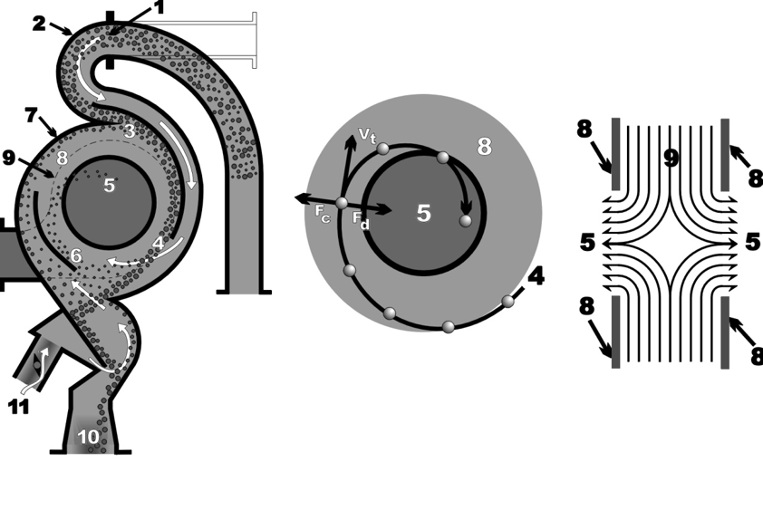
The design and unique operating functions of the Centrifugal Classifier are detailed in Figures 5, 6 and 7.

Feed material and gas (usually air) enter the classifier inlet (1). The connecting duct for pneumatically conveyed material can be positioned from a vertical to a horizontal position to suit layout requirements (see dashed outline Figure 5). Gas inlet velocity is based upon feed material physical characteristics and cut point. Conveying velocity may be higher. For pneumatically fed, open air systems, the classifier inlet is flared and the feed dropped directly into the air stream.
The sharp bend (2) behind the inlet separates feed material from the gas steam by centrifugal action. The resultant “clean” gas stream passes behind a baffle plate (3) against which the feed material is sliding. The air stream then crosses the curtain of feed material (4) producing an intense scrubbing action which separates fine particles from the tailings, breaks up agglomerates and subjects all particles to an equal drag force.
Gravitational force immediately precipitates any very large particles to the bottom of the classifier. Intermediate and finer particles flow with the gas stream in a spiral path around the exhaust orifice (5) and are classified. The baffle plates (3, 6), the classifier outer casing (7), and side plates (8) form a flat, cylindrical classifying chamber (9) through which the gas stream spirals inwardly in a two-dimensional flow.
Each particle is subjected to centrifugal force (Fc) proportional to the cube of its diameter, causing the particle to move toward the periphery of the chamber. Concurrently, the gas stream is exerting a drag force (FD) directly proportional to the diameter of the particle. Under design conditions, the centrifugal force (Fc) equals the drag force (FD) of a particular particle diameter (K) (cut point). These two opposing forces which are in equilibrium only at cut point separate feed particles into two groups. Centrifugal force (Fc) causes particles larger than cut point (greater mass) to be propelled outwardly, impinging on the peripheral walls; their velocity is slowed; gravity causes them to settle to the bottom of the classifier. Drag force (FD) causes particles smaller than cut point (lower mass) to be swept inwardly and discharged with the gas stream through the orifice (5) where they are collected by a filter.
To obtain sharp separation, forces acting on each cut-point particle (K) must be in equilibrium through the classifying chamber assuring that every introduced particle is subjected to the same separation influence. The centrifugal classifier uniquely meets this requirement with its method of introducing feed material and gas flow into the classifying chamber to form a controlled vortex with a constant velocity profile. Appropriate classifying chamber proportions and specialized orifice design eliminate detrimental frictional drag effect from the chamber side walls (8) without moving parts.
Centrifugal classifiers separate at any desired cut point from 15 to 100 microns. The cut point is controlled by the vortex flow path steepness, the tangential velocity (VT) and the absolute dimensions of the classifying chamber. The flow path is controlled by the ratio of exhaust orifice diameter to the classifying chamber diameter and the amount of secondary air introduced at the bottom of the unit (11). Customers’ varying cut point requirements are met by regulating secondary air flow.
Power requirements are low.
Summary
Van Tongeren classifiers are available in a wide range of capacities for sizing, de-dusting or de-fuming dry particulates at feed rates from a few pounds per hour to 600 tons per hour. Three basic models are available, each offering cut point control in different size ranges.
- The Gravitational classifier is ideally suited for coarser cuts ranging from 2 mm to 150 microns (10 to 100 mesh).
- The Gravitational-Inertial classifier utilizes increased air velocities and it is designed for cut points from 300 to 63 microns (50 mesh to 230 mesh).
- The Centrifugal classifier requires less handling equipment and ranges from 100 microns to 15 microns.
For the classification of dry solids between 10 mesh and 15 microns, pneumatic classifiers have several advantages over screens:
- Lower capital cost
- Lower operating cost
- Lower maintenance cost
- Greater on-line dependability
- Product efficiency
Most fine particulate separation requirements are more than satisfied by pneumatic classification. Table 1 illustrates a partial list of materials which can be classified with the Van Tongeren classifiers:
|
TABLE 1 |
|||
| Alumina | Fertilizer | Lime | Sand |
| Catalyst | Fly ash | Limestone | Silica |
| Cement | Gold/Silver dust | Potash | Soda ash |
| Chrome ore | Granular chemicals | Phosphate rock | |
| Diatomaceous earth | Iron ore | Salt | |
